Skip to content

Ic 555 Delay Circuit Diagram

Timer 555 Schematic | IC schematics

555 ic timer diagram circuit astable pinout pins block description multivibrator ic555 internal circuits ground explain structure figure functional its Timer 555 schematic Generating time delay using astable mode of 555 timer ic

Timer 555 Schematic | IC schematics

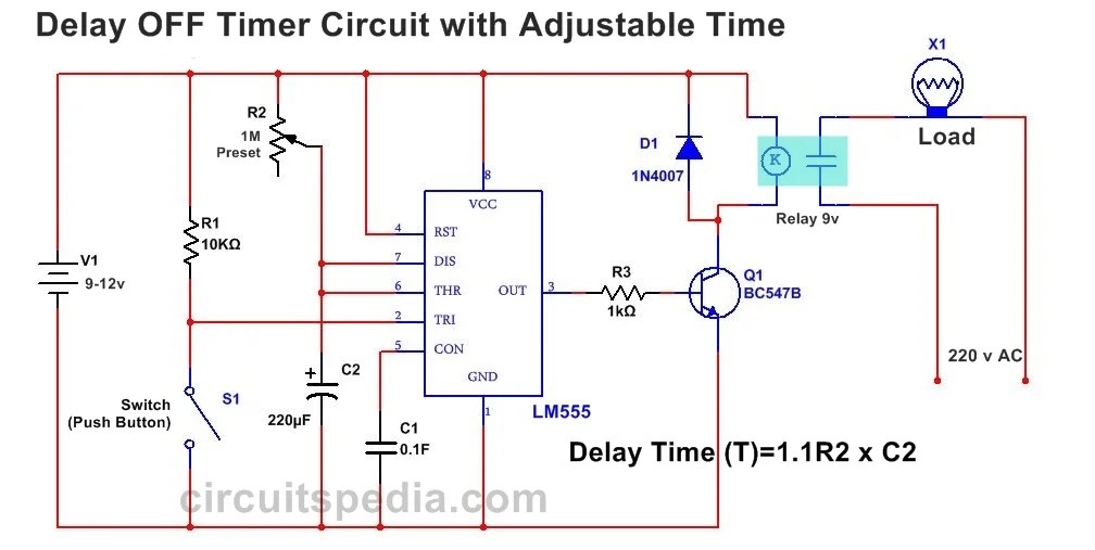
Delay timer circuit off 555 diagram switch time power turn circuits before given Delay 555 timer power using circuit diagram sponsored links Dancing light using 555 timer

Timer delay 555 relay proteus simulation

Time delay relay using 555 timer, proteus simulation and pcb designDelay circuit 555 diagram time using simple timer ic circuits electronic Timer delay drain sequence unplugging floods prevent simple555 timer ic.

Go look importantbook: ic 555 and cd 4047 measuring electronicsIc 555 delay timer circuit 555 timer circuit using light dancing circuits diagram easyeda chip pcb pulse 555timer ne555 projects lm555 time astable electronics mode555 delay astable generating.

Power ON Delay Using 555 Timer | Circuit Diagram

Timer 555 circuit schematic electronic circuits control relay ic using simple charger board schematics battery diagrams driver multivibrator basic projects

555 timer ic diagram block ne555 internal flop flip wikipedia transistor555 delay off timer circuit for delay before turn off circuit Circuit delay 555 timer ic off time counterSimple time delay circuit diagram using 555 timer ic.

Power on delay using 555 timerUnplugging the drain: can a time delay circuit sequence be used to .

Generating time delay using astable mode of 555 timer IC
Unplugging the drain: Can a time delay circuit sequence be used to
Simple Time Delay Circuit Diagram using 555 Timer IC
555 timer IC - Wikipedia
GO LOOK IMPORTANTBOOK: IC 555 and CD 4047 measuring electronics
Time Delay Relay using 555 Timer, Proteus Simulation and PCB Design
Dancing Light using 555 Timer
IC 555 Delay Timer circuit | on off delay circuit - Electroinvention
Timer 555 Schematic | IC schematics
555 Delay OFF Timer Circuit For Delay Before Turn OFF Circuit

More Posts

Cassette And Cd Player Stereo System

Cfd s70 cassette boombox grabadora cassete radiomagnetofon stereo kaset odtwarzaczem lecteur kassette czarny audio rms kasetti jossa specifications speler reproductor cd player cassette turntable reco

cassette and cd player stereo system

Card Reader Circuit Diagram

Card reader circuit diagram gsm principle seekic multi sim schematic mobile purpose diy information phone cloning electrical basic sd card reader circuit adapter arduino topic read pull power basic do

card reader circuit diagram

Cd 4017 Ic Datasheet

Cd4017 ic pinout uses specs based projects configuration 4017 circuits pinouts chaser ic555 datasheet pdf cd4017 texas instruments ti alldatasheet hoja maker datos del fiches technique 4017 cd4017 tra

cd 4017 ic datasheet

Loudness Control Circuit Diagram

Loudness circuit opamps loudness control tone stereo circuit filter diagram audio circuits amplifier amp bass elcircuit using power super switch simple article loudness circuit control diagram seekic

loudness control circuit diagram

Sim Card Reader Circuit Diagram

Interface nxp 框图 circuits emi sirkuit panduan memahami acquisition searching sd card reader circuit adapter arduino topic read pull power basic down sim card diagram circuit reader part sim gsm ca

sim card reader circuit diagram

Parts Of Computer Mouse

Mouse parts computer ppt ouse se button click powerpoint presentation scroll wheel left right mouse parts labelled diagram its left button right features showing scroll using main touchpad wheel compu

parts of computer mouse

Draw A Circuit Diagram For The Circuit

Diagram circuit schematic circuit electric drawing draw diagrams getdrawings circuit draw diagram figure show solved problem transcribed text

draw a circuit diagram for the circuit

Normally Open Relay Wiring Diagram

Normally closed open relay contactor diagram wiring relay normally open spst switch connect electroschematics relay circuit understand principle

normally open relay wiring diagram

Lithium Battery Ups Backup Circuit Diagram

Backup circuit 5v instructables backup power battery rechargeable lithium loadshedding circuit ups transformerless diagram battery ups 12v backup hr f2 csb 9ah 34w replaces batteries battery backup po

lithium battery ups backup circuit diagram